Hacking My House #1: Building a Musical Arduino Doorbell
Earlier this year my family and I had the good fortune to move to our first home. Â The home had everything we wanted, except a working doorbell.
The original doorbell button was there, complete with decades of corrosion and wires that were cut between the button and what looked to be some sort of buzzer. Initially, I planned to buy a new chime and button at Home Depot, hook up the wires, and be done with it. The chime selection, however, was sub-par.
Apparently the doorbell market is dominated by ding-dong and Westminster. Growing up, my father built a doorbell that played the first two measures of Pictures at an Exhibition. Maybe I was spoiled listening to this during my formative years, but if I wanted a doorbell that played music, I needed to build it myself.
The doorbell design
The general design of the doorbell circuit is pretty straight forward. The music is generated by an Arduino Uno, programmed to create sound using Pulse Width Modulation. This output is passed through a low pass filter to improve the tonality. The low pass filter is then fed into an LM386 audio amplifier, which is hooked to a speaker. Pin 12 on the Arduino is used as the button trigger.
The code
The following code is based on code from 30 Arduino Projects For The Evil Genius, which is a great book for anyone looking for some fun Arduino projects. The code for the entire book is released open source, which makes it possible to share with my modifications here.
The code creates a sine wave signal that generates sound by controlling the modulation width. A sine wave is preferable to a square wave, as it generates better quality sound. Each note is created by increasing and decreasing the small delays in the sine wave signal output. To tune my scales, I used this nice virtual keyboard to match the correct pitch for each note.
const int buttonPin = 12;
int buttonState = 0;
int playSong = 0;

int dacPins[] = {2, 4, 7, 8};

int sin16[] = {7, 8, 10, 11, 12, 13, 14, 14, 15, 14, 14, 13, 12, 11,
              10, 8, 7, 6, 4, 3, 2, 1, 0, 0, 0, 0, 0, 1, 2, 3, 4, 6};

int lowToneDurations[] = {120, 105, 98, 85, 72, 68, 57};
//                        A    B    C   D   E   F   G
int highToneDurations[] = { 49, 41, 37, 31, 25, 23, 18 };
//                          a   b   c   d   e   f   g

// Scale
//char* song = "A B C D E F G a b c d e f g";

// Jingle Bells
//char* song = "E E EE E E EE E G C D EEEE F F F F F E E E E D D E DD
//              GG E E EE E E EE E G C D EEEE F F F F F E E E G G F D CCCC";

// Jingle Bells - Higher
//char* song = "e e ee e e ee e g c d eeee f f f f f e e e e d d e dd gg
//              e e ee e e ee e g c d eeee f f f f f e e e g g f d cccc";

// Pictures at an Exhibition
char* song = "DD CC FF G c aa G c aa FF GG DD CC";


void setup()
{
  for (int i = 0; i < 4; i++)
  {
    pinMode(dacPins[i], OUTPUT);
  }
}


void loop()
{
    buttonState = digitalRead(buttonPin);

    if (buttonState == LOW)
    {
        playSong = 1;
    }
    else
    {
        playSong = 0;
    }

    if(playSong == 1)
    {
        int i = 0;
        char ch = song[0];
        while (ch != 0)
        {
            if (ch == ' ')
            {
                delay(60);
            }
            else if (ch >= 'A' and ch <= 'G')
            {
                playNote(lowToneDurations[ch - 'A']);
            }
            else if (ch >= 'a' and ch <= 'g')
            {
                playNote(highToneDurations[ch - 'a']);
            }
            i++;
            ch = song[i];
        }
    }
}


void setOutput(byte value)
{
    digitalWrite(dacPins[3], ((value & 8) > 0));
    digitalWrite(dacPins[2], ((value & 4) > 0));
    digitalWrite(dacPins[1], ((value & 2) > 0));
    digitalWrite(dacPins[0], ((value & 1) > 0));
}


void playNote(int pitchDelay)
{
  long numCycles = 5000 / pitchDelay + (pitchDelay / 4);
  for (int c = 0; c < numCycles; c++)
  {

    for (int i = 0; i < 32; i++)
    {
      setOutput(sin16[i]);
      delayMicroseconds(pitchDelay);
    }
  }
}
The Arduino Stage
The Arduino stage feeds the pin output into a resistor ladder, which creates the PWM signal, which is fed into a low pass filter. The low pass filter transforms the signal to sound a little cleaner. While I knew I needed a low pass filter here, I wasn't sure what design to use. My father gets credit here for pointing me in the right direction. Â The sound output is controlled through a button hooked up to pin 12 on the Arduino, that listens for the closed state.
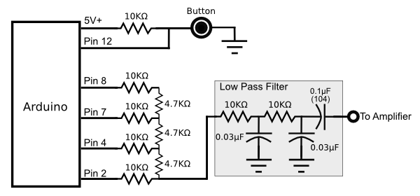
Arduino Pulse Width Modulation (PWM) schematic
The LM386 Amplifier Stage
I ran into some difficulties with the LM386 amplifying miscellaneous noise artifacts, not limited to it picking up local AM radio. At one point I was picking up the radio signals so clearly, I might try making a cheap LM386 powered radio. In either case, some well placed capacitors cleaned things up.
I also included a 10mF capacitor between pins 1 and 8 to increase the volume, and included the 0.33mF capacitor with the 10K ohm resistor from pins 5 to 1 to add some bass boost, again to improve the tonality. These modifications are listed on the standard LM386 datasheet for those interested.
The speaker I chose was an old computer speaker I had laying around. Â I cut down the case and spray painted it ivory to improve how it looks mounted to the wall.
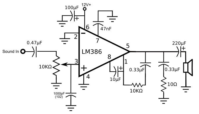
LM386 amplifier schematic
 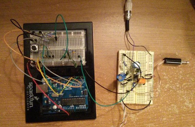
The above two schematics on the breadboard
Using a fancy doorbell button
At this point I could have probably wrapped up the project, but after all the effort, I couldn't just use any button. I went out to Home Depot and picked up one of those fancy buttons that lights up. I promptly supplied 12V to the button, hooked it up to my circuit, and found out that my circuit always saw the button as on. Â (A simple button that makes an open/closed contact point when pushed will work fine with the above circuit.)
After some experimentation, I noticed that when the button was not pressed, the voltage output was about 12 volts. When pressed it dropped down to something like 2 volts. I knew if I used a few transistors I could probably trick my circuit into thinking the fancy button was a simple open-close button.
Again, the credit for this next module goes to my father. I'm admittedly novice when it comes to circuit design, and wasn't exactly sure how to design this.
When the voltage is close to 12V the circuit is closed. When it drops significantly, the circuit is open.
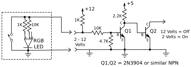
 Transistor voltage inverter schematicÂ
I also ran into another problem. The button required a resistor at the 12V input or the button would short out the power supply each time it was pressed. Since the button had a small incandescent light inside, it sucked up a ton of power, and was quickly over heating a low wattage resistor. Two options were on the table: 1) Use a huge high wattage resistor, or 2) take apart the doorbell and replace the bulb with an LED. The LED seemed to be the better of the two options.
I decided to use an RGB LED, since I could control the color of the button and because they are pretty bright. I used a 10K ohm resistor on the green pin and a 1K ohm resistor on the red pin to create a nice orange color, similar to the color generated by the original bulb.
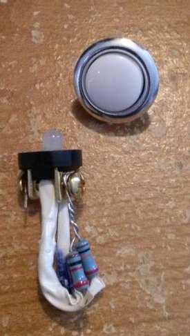
Modified LED doorbell button
Final product
I mounted everything in one of those blue plastic electrical boxes. An added benefit was that the perf boards I purchased fit snugly into the slots of the box, so I could install each cleanly.
Here are some pictures of the final product:
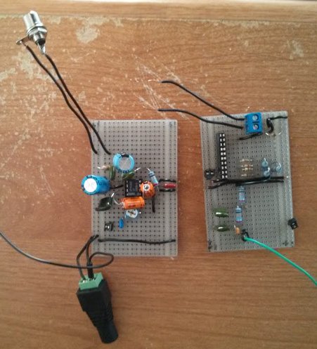
The Arduino stage and LM386 stage soldered up
 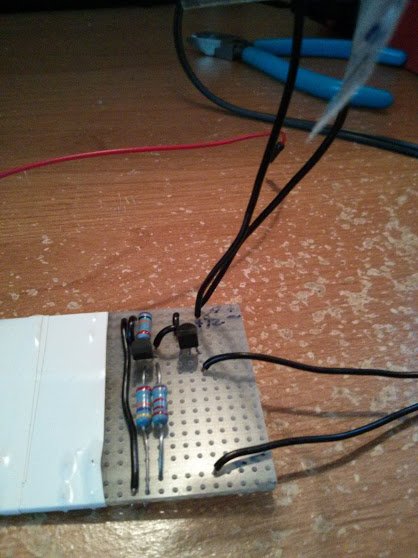
Transistor circuit
 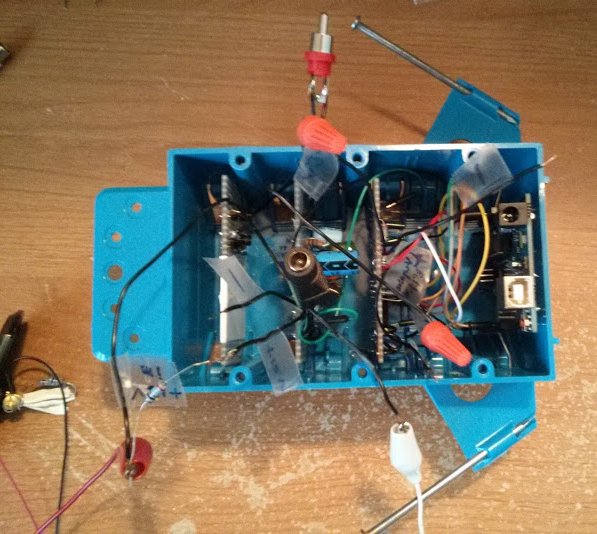
Final Arduino doorbell enclosure
And I'm sure you want to hear what the doorbell sounds like:
Ahh... music to my ears!
Update: Read my part 2 post with an improvment to the doorbell design.
Posted: Mar 27, 2013
Keyword tags: arduinocircuitselectronicsdoorbellschematiclm386
Recent Posts:
Popular Posts:
Recent Security Posts:
S3 Buckets: Now With Both Leak & Fill Vulnerability
Stealing Data With CSS: Attack and Defense
Move Over S3: Open Directory Indexes Continue to be a Problem
Security Researchers Lose a Favorite DNS Recon Tool Jan 2018
KRACK: How To Protect Yourself on a Flawed Network
Equifax, SEC, & Now Deloitte: Organizations Must Employ Offensive Security
