mike gualtieri :: homepage ~ #
Build an Arduino Word Clock
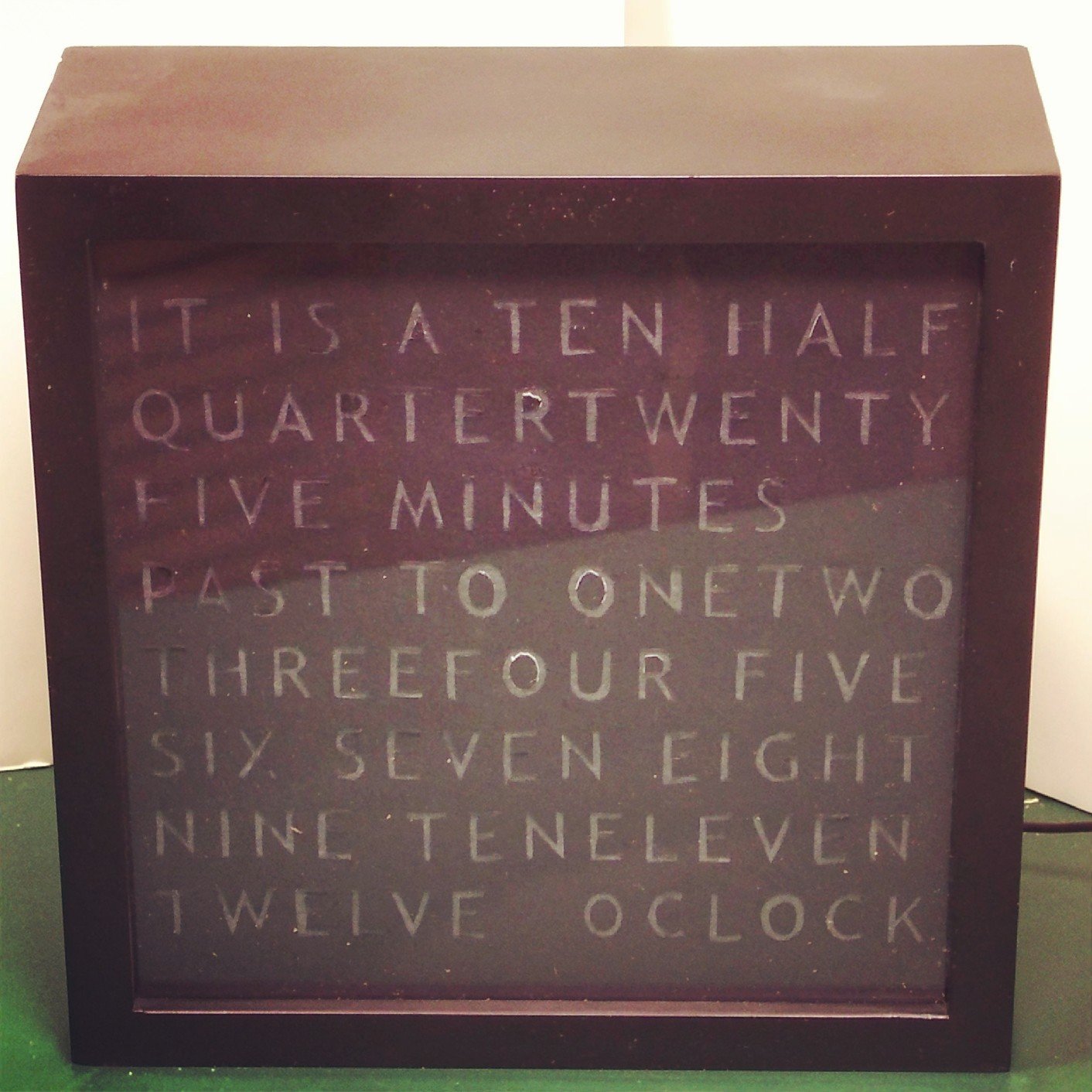
A few months ago I came across an interesting project, an Arduino Word Clock.  If you aren't familiar with the term, it's basically a clock that tells you the time as a sentence instead of with digits.  So instead of 10:30pm, it would say, it is half past ten.  The reported time accuracy is within 5 minutes, which is good enough for a general clock / interesting piece of art.  I decided to build one as a Christmas present for my dad.
Although I read a few different designs on the web, I decided to take my own path and design my own. Â I encourage you to do the same; sometimes it's easier to do things the way you want to do them and look to others for inspiration, than follow instructions to the last detail.
The general steps are: 1) Create the clock face, 2) Wire the lights, 3) Build the driver for the lights, 4) Add the clock, and 5) Final assembly.
Creating the clock face
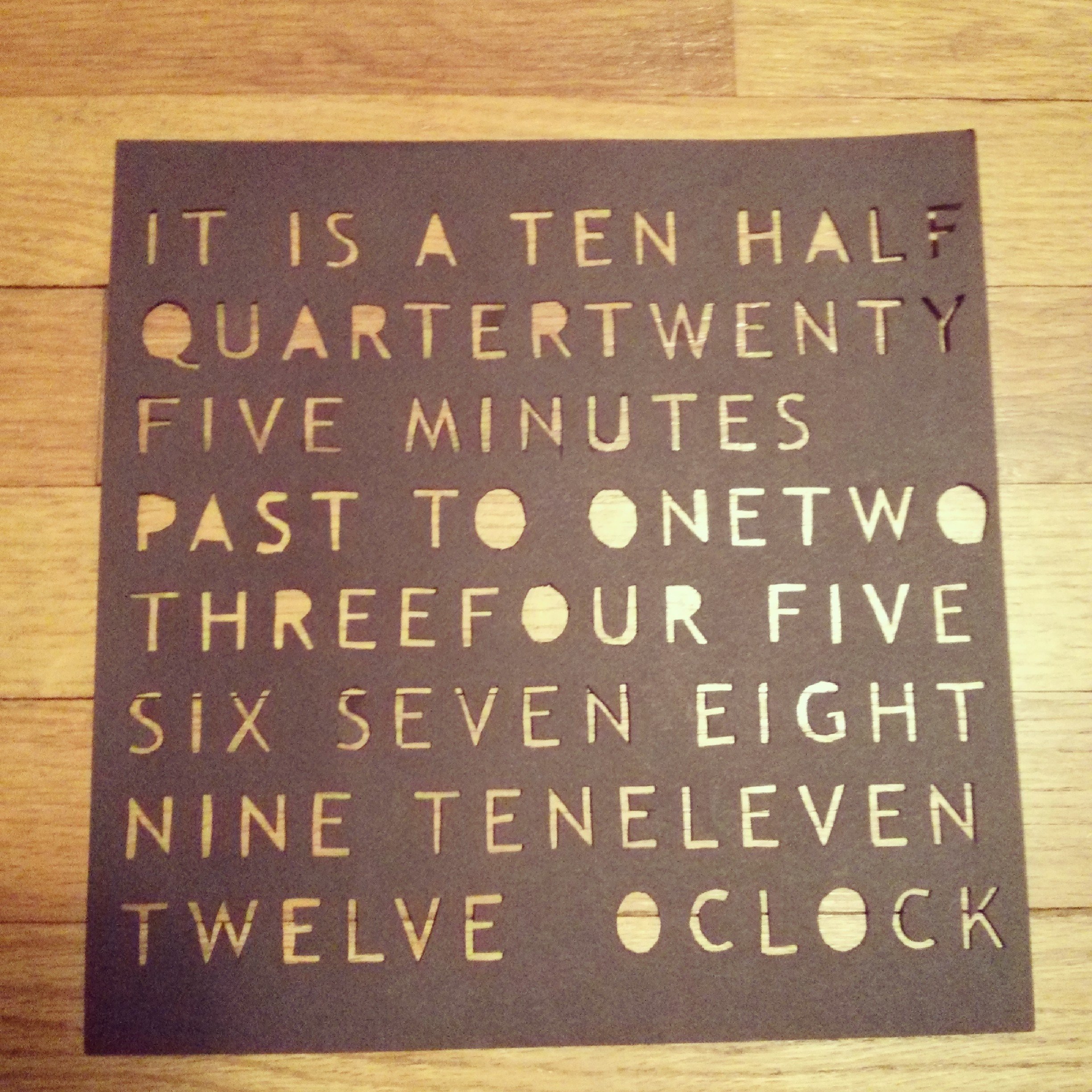
I started to create the clock face by planning out the word placement. Â I went with a layout like this, that has 23 words:IT ISATENHALF
QUARTERTWENTY
FIVE MINUTES
PASTTO ONETWO
THREEFOURFIVE
SIXSEVENEIGHT
NINETENELEVEN
TWELVE OCLOCK

Wiring the LEDs
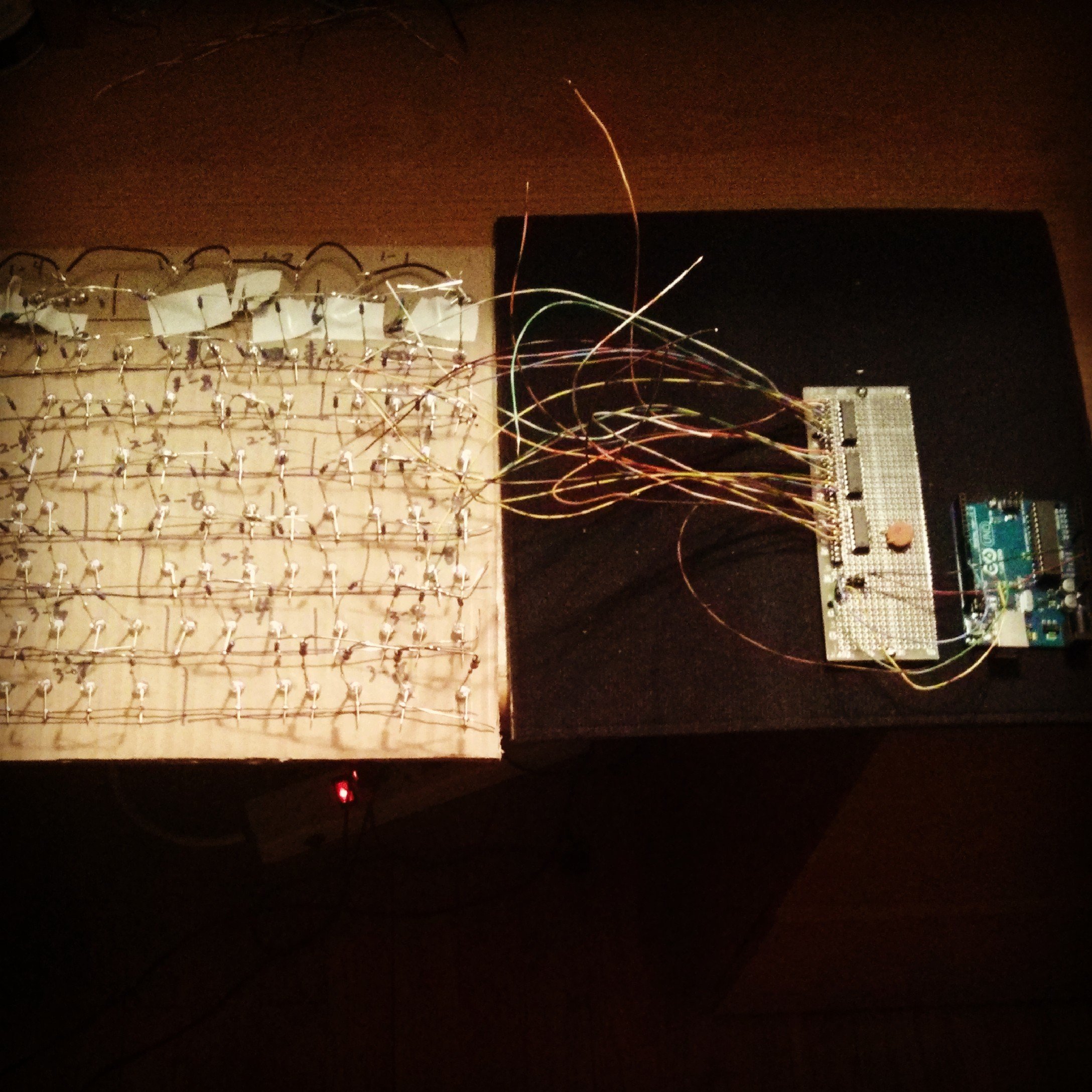
This was also a time consuming process, mainly due to soldering a resistor to each of the 99 LEDs. Â Each word was soldered up in parallel, and connected to a pin on a shift register (more on that later). Â I went with individual LEDs for each letter, to ensure an even amount of light would be illuminated behind each letter. Â In retrospect, I wonder if using some LED strips would have looked good enough. Â It's a good idea to label each group so you won't make any mistakes while soldering. Â For ground, I used a strip of bare wire along each row. Â Since the shadow box that would be my final mount had a lot of room, I kept the positive lead on the LEDs sticking straight up.
Building the Arduino Driver
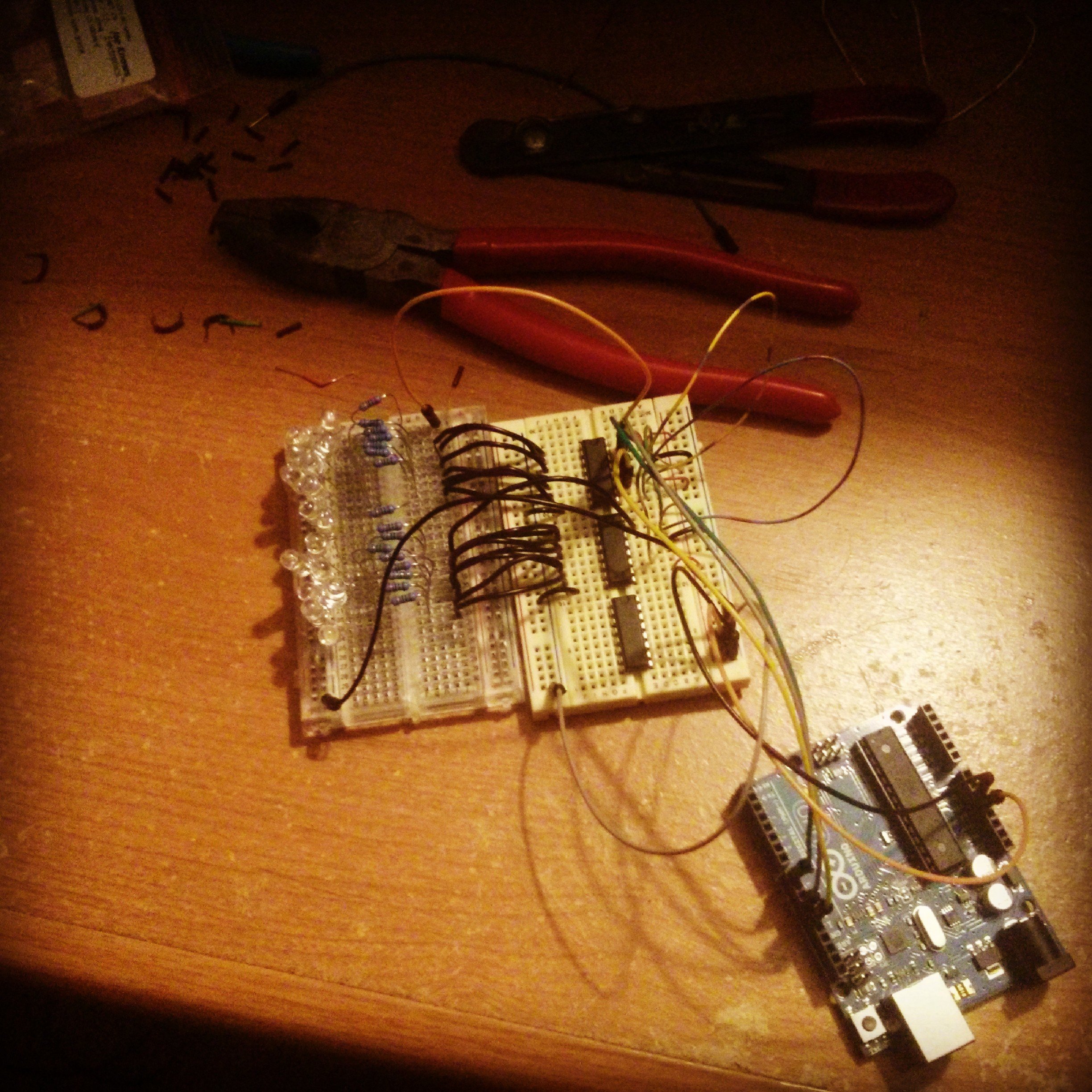
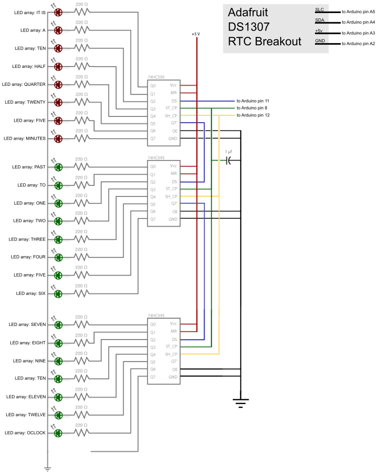
With the need to drive lights for 23 words, we will need to use shift registers, as the Arduino UNO doesn't have 23 pin outs.  If you don't know what a shift register is, it's basically a memory buffer that can be used to control a larger set of outputs from a smaller set.  In our case, we will use 3 pins from the Arduino to drive three 8-bit 74HC595 shift registers.  So, from three pins we can control up to 24 output states.The nice part of the 74HC595, is that they can be chained together.  Theoretically you could have infinite pins under your control.
Before I soldered things up, I created a small prototype to ensure I was able to properly control each LED group. Â The Arduino ShiftOut tutorial was quite helpful here.
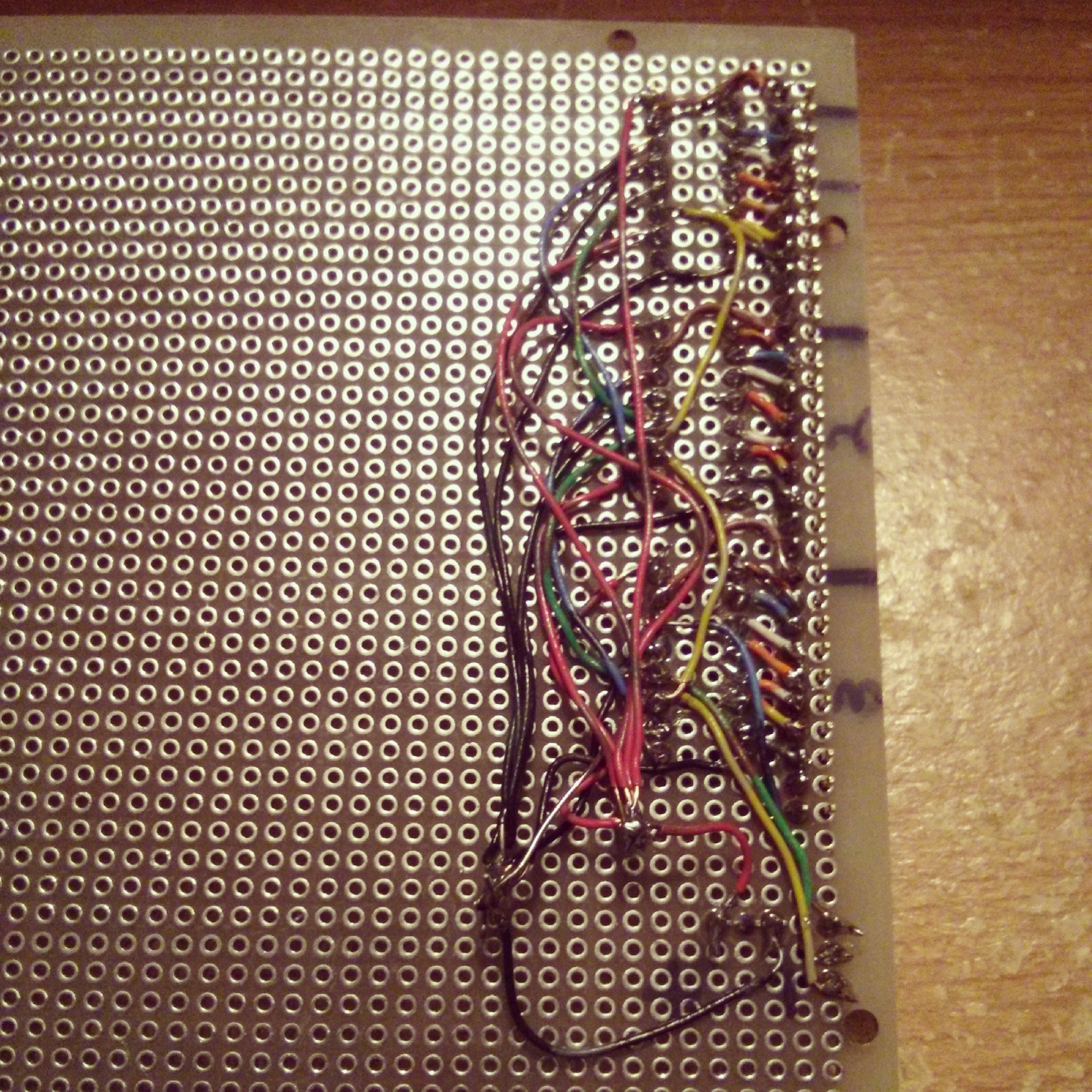
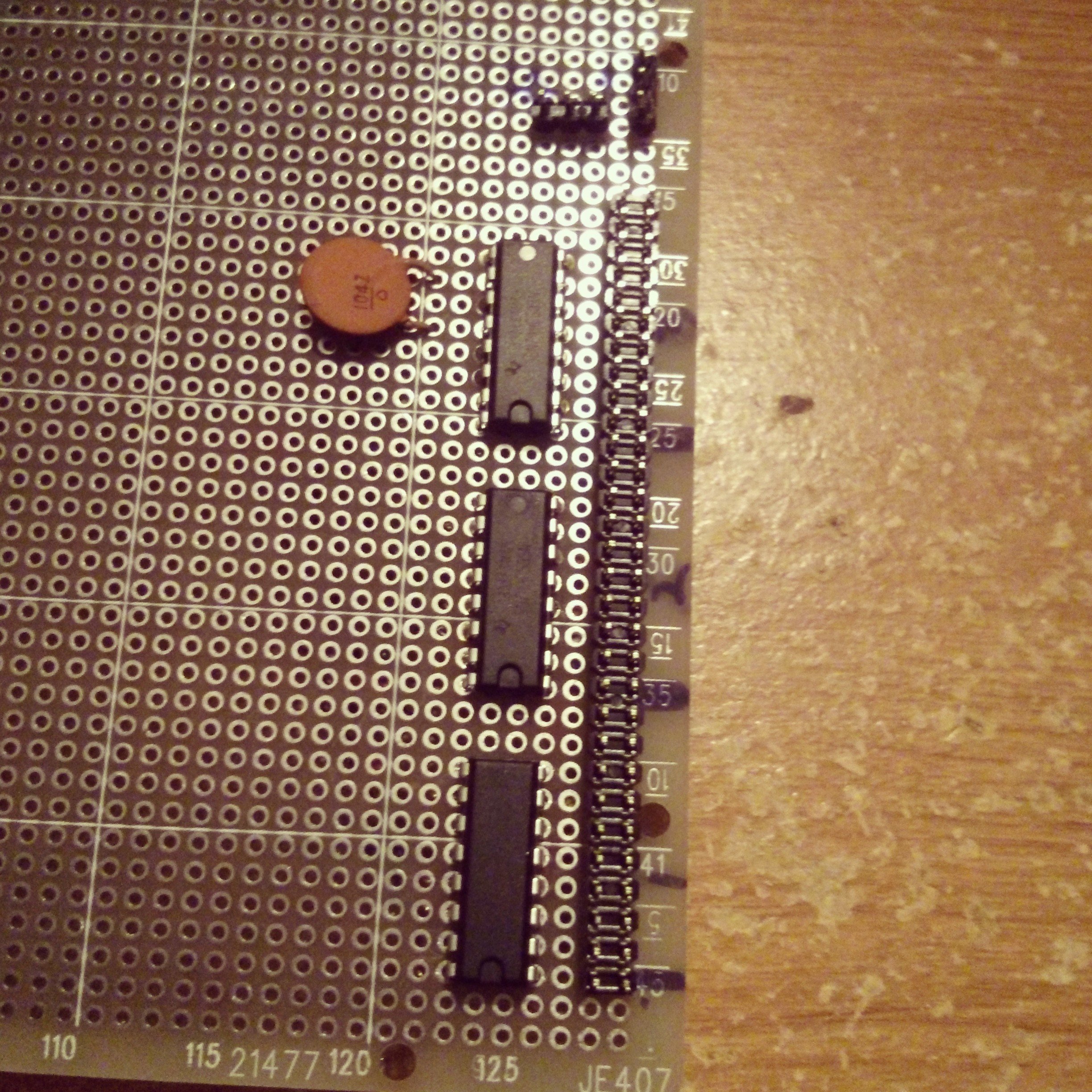
After everything was working well, I soldered it up on some perf board. Â Again, this was time consuming as there were many connections to make.
Adding the clock
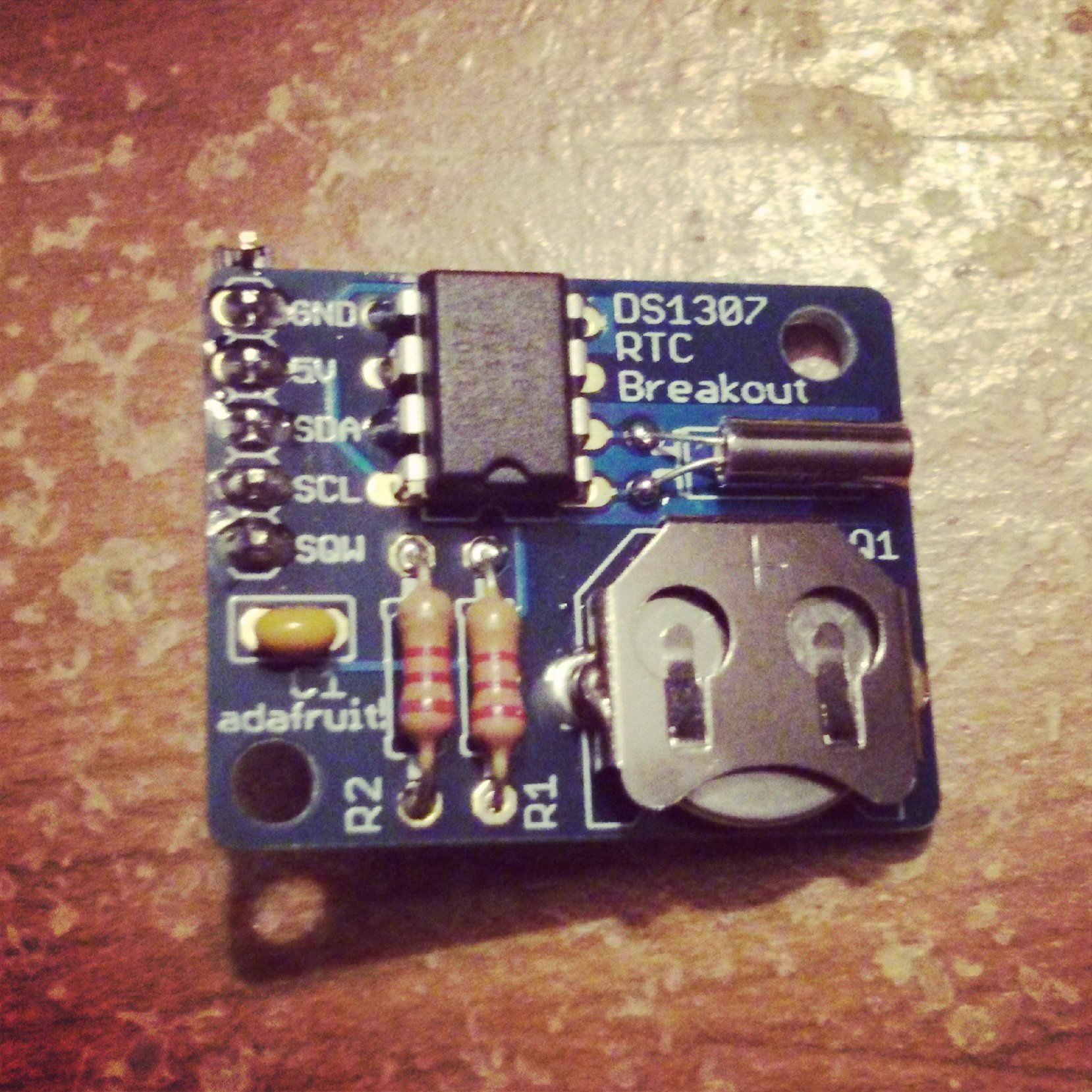
A clock is only good if it can tell accurate time.  And, it didn't seem like a great option to build a bunch of controls to set the time each time it's powered up.  Instead I opted to add a battery backup RTC (Real Time Clock) to the device.  Luckily Adafruit sells an Arduino RTC breakout board based on the popular DS1307 IC.  Their tutorial was also quite helpful.A small aside:  I ran into trouble getting the breakout to work.  The issue was a crossdev toolchain problem with the RTC library and my Gentoo Linux laptop.  Details about the issue are on the Adafruit forums. Chances are very few people will run into this same issue.
Final assembly
If you are reading this deep in the article, you are probably wondering about the code used to power the clock. Â Before I wrote any code, I created these maps to show which register and pin should be lit for each word.reg pin
0 Â 0 Â IT IS
0 Â 1 Â A
0 Â 2 Â TEN
0 Â 3 Â HALF
0 Â 4 Â QUARTER
0 Â 5 Â TWENTY
0 Â 6 Â FIVE
0 Â 7 Â MINUTES
1 Â 0 Â PAST
1 Â 1 Â TO
1 Â 2 Â ONE
1 Â 3 Â TWO
1 Â 4 Â THREE
1 Â 5 Â FOUR
1 Â 6 Â FIVE
1 Â 7 Â SIX
2 Â 0 Â SEVEN
2 Â 1 Â EIGHT
2 Â 2 Â NINE
2 Â 3 Â TEN
2 Â 4 Â ELEVEN
2 Â 5 Â TWELVE
2 Â 6 Â OCLOCK
For all: IT IS OCLOCK 0-0, 2-6
1:00 IT IS ONE OCLOCK Â Â Â Â Â Â Â Â Â Â Â Â Â Â Â N
1:05 IT IS FIVE MINUTES PAST ONE OCLOCK Â Â Â Â Â Â 0-6, 1-0, N
1:10 IT IS TEN MINUTES PAST ONE OCLOCK Â Â Â Â Â Â Â 0-2, 0-7, 1-0, N
1:15 IT IS A QUARTER PAST ONE OCLOCK Â Â Â Â Â Â Â Â 0-1, 0-4, 1-0, N
1:20 IT IS TWENTY MINUTES PAST ONE OCLOCK Â Â Â Â Â 0-5, 0-7, 1-0, N
1:25 IT IS TWENTY FIVE MINUTES PAST ONE OCLOCK Â Â Â 0-5, 0-6, 0-7, 1-0, N
1:30 IT IS HALF PAST ONE OCLOCK Â Â Â Â Â Â Â Â Â Â 0-3, 1-0, N
1:35 IT IS TWENTY FIVE MINUTES TO TWO OCLOCK Â Â Â Â 0-5, 0-6, 0-7, 1-1, N+1
1:40 IT IS TWENTY MINUTES TO TWO OCLOCK Â Â Â Â Â Â 0-5, 0-7, 1-1, N+1
1:45 IT IS A QUARTER TO TWO OCLOCK Â Â Â Â Â Â Â Â Â 0-1, 0-4, 1-1, N+1
1:50 IT IS TEN MINUTES TO TWO OCLOCK Â Â Â Â Â Â Â Â 0-2, 0-7, 1-1, N+1
1:55 IT IS FIVE MINUTES TO TWO OCLOCK Â Â Â Â Â Â Â 0-6, 0-7, 1-1, N+1
2:00 IT IS TWO OCLOCK Â Â Â Â Â Â Â Â Â Â Â Â Â Â Â N
Here's the code with comments to explain how things work. Â The code was heavily based on the ShiftOut and RTC examples, with some additional logic needed for this specific application.
#include < wire.h >
#include "RTClib.h"
RTC_DS1307 RTC;
// Pin connected to ST_CP of 74HC595
int latchPin = 8;
// Pin connected to SH_CP of 74HC595
int clockPin = 12;
// Pin connected to DS of 74HC595
int dataPin = 11;
// Holders for information you're going to pass to shifting function
byte dataArray[10];
byte dataToSend[3];
void setup() {
 // Set pins to output because they are addressed in the main loop
 pinMode(latchPin, OUTPUT);
 Serial.begin(9600);
 Wire.begin();
 RTC.begin();
// Set pins A2 and A3 so we can power the RTC breakout directly from each
 pinMode(A2, OUTPUT);
 digitalWrite(A2, LOW);
 pinMode(A3, OUTPUT);
 digitalWrite(A3, HIGH);
Â
 if (! RTC.isrunning()) {
   Serial.println("RTC is NOT running!");
   // following line sets the RTC to the date & time this sketch was compiled
   RTC.adjust(DateTime(__DATE__, __TIME__));
 }  Â
// These are the bitmasks used to set the shift registers
// states 0 - 7 set one of each of the pins to be on
// state 8 turns all the pins on, and state 9 sets them all off
 dataArray[0] = 0x01; //00000001
 dataArray[1] = 0x02; //00000010
 dataArray[2] = 0x04; //00000100
 dataArray[3] = 0x08; //00001000
 dataArray[4] = 0x10; //00010000
 dataArray[5] = 0x20; //00100000
 dataArray[6] = 0x40; //01000000
 dataArray[7] = 0x80; //10000000
 dataArray[8] = 0xFF; //11111111
 dataArray[9] = 0x00; //00000000
 // Function that blinks all the LEDs, feel free to eliminate...
// I got it directly from the Arduino ShiftOut tutorial and kept it in
 blinkAll_2Bytes(2,500);
// Just runs through all the clock states each time its powered on...
// Feel free to eliminate
 testAllStates();Â
}
void loop()Â
{
// Get the current hour and minute
  DateTime now = RTC.now();
  int hour = now.hour();
  int min  = now.minute();
// Print statements for debugging
  /*
  Serial.print(now.hour(), DEC);
  Serial.print(':');
  Serial.print(now.minute(), DEC);
  Serial.println();
  */
  Â
// We need to set the latch to 0 before each set of pin writes
  digitalWrite(latchPin, 0); Â
  // IT IS and OCLOCK are lit in all states
  // Also initialize register 1 to 0's
  dataToSend[0] = dataArray[0];
  dataToSend[1] = dataArray[9];
  dataToSend[2] = dataArray[6];
  // Add bytes needed to light other pins
  if(min < 5)
  {
    //1:00 IT IS ONE OCLOCK
    // no need to light anything else
  }
  else if(min < 10)
  {
    //1:05 IT IS FIVE MINUTES PAST ONE OCLOCK
    dataToSend[0] += dataArray[6];
    dataToSend[1] += dataArray[0];
  }
  else if(min < 15)
  {
    //1:10 IT IS TEN MINUTES PAST ONE OCLOCK
    dataToSend[0] += dataArray[2] + dataArray[7];
    dataToSend[1] += dataArray[0];
  }
  else if(min < 20)
  {
    //1:15 IT IS A QUARTER PAST ONE OCLOCK
    dataToSend[0] += dataArray[1] + dataArray[4];
    dataToSend[1] += dataArray[0];    Â
  }
  else if(min < 25)
  {
    //1:20 IT IS TWENTY MINUTES PAST ONE OCLOCKÂ
    dataToSend[0] += dataArray[5] + dataArray[7];
    dataToSend[1] += dataArray[0];
  }
  else if(min < 30)
  {
    //1:25 IT IS TWENTY FIVE MINUTES PAST ONE OCLOCK
    dataToSend[0] += dataArray[5] + dataArray[6] + dataArray[7];
    dataToSend[1] += dataArray[0];
  }
  else if(min < 35)
  {
    //1:30 IT IS HALF PAST ONE OCLOCKÂ
    dataToSend[0] += dataArray[3];
    dataToSend[1] += dataArray[0];
  }
  else if(min < 40)
  {
    //1:35 IT IS TWENTY FIVE MINUTES TO TWO OCLOCK
    dataToSend[0] += dataArray[5] + dataArray[6] + dataArray[7];
    dataToSend[1] += dataArray[1];
  }
  else if(min < 45)
  {
    //1:40 IT IS TWENTY MINUTES TO TWO OCLOCK
    dataToSend[0] += dataArray[5] + dataArray[7];
    dataToSend[1] += dataArray[1];
  }
  else if(min < 50)
  {
    //1:45 IT IS A QUARTER TO TWO OCLOCK
    dataToSend[0] += dataArray[1] + dataArray[4];
    dataToSend[1] += dataArray[1];
  }
  else if(min < 55)
  {
    //1:50 IT IS TEN MINUTES TO TWO OCLOCK
    dataToSend[0] += dataArray[2] + dataArray[7];
    dataToSend[1] += dataArray[1];
  }
  else if(min < 60)
  {
    //1:55 IT IS FIVE MINUTES TO TWO OCLOCK
    dataToSend[0] += dataArray[6] + dataArray[7];
    dataToSend[1] += dataArray[1];
  }
  // Set hour register and pin
  if(min < 35)
  {
    int reg = getHourRegister(hour);
    int pin = getHourPin(hour);
    dataToSend[reg] += dataArray[pin];
  }
  else
  {
    int reg = getHourRegister(hour + 1);
    int pin = getHourPin(hour + 1);
    dataToSend[reg] += dataArray[pin];
  }
    Â
  shiftOut(dataPin, clockPin, dataToSend[0]);
  shiftOut(dataPin, clockPin, dataToSend[1]); Â
  shiftOut(dataPin, clockPin, dataToSend[2]); Â
  Â
  Â
  digitalWrite(latchPin, 1);
  delay(5000);
}
// the heart of the program
void shiftOut(int myDataPin, int myClockPin, byte myDataOut) {
 // This shifts 8 bits out MSB first,Â
 //on the rising edge of the clock,
 //clock idles low
 //internal function setup
 int i=0;
 int pinState;
 pinMode(myClockPin, OUTPUT);
 pinMode(myDataPin, OUTPUT);
 //clear everything out just in case to
 //prepare shift register for bit shifting
 digitalWrite(myDataPin, 0);
 digitalWrite(myClockPin, 0);
 //for each bit in the byte myDataOut
 //NOTICE THAT WE ARE COUNTING DOWN in our for loop
 //This means that %00000001 or "1" will go through such
 //that it will be pin Q0 that lights.Â
 for (i=7; i>=0; i--)  {
  digitalWrite(myClockPin, 0);
  //if the value passed to myDataOut and a bitmask resultÂ
  // true then... so if we are at i=6 and our value is
  // %11010100 it would the code compares it to %01000000Â
  // and proceeds to set pinState to 1.
  if ( myDataOut & (1<<i) ) {
   pinState= 1;
  }
  else {  Â
   pinState= 0;
  }
  //Sets the pin to HIGH or LOW depending on pinState
  digitalWrite(myDataPin, pinState);
  //register shifts bits on upstroke of clock pin Â
  digitalWrite(myClockPin, 1);
  //zero the data pin after shift to prevent bleed through
  digitalWrite(myDataPin, 0);
 }
 //stop shifting
 digitalWrite(myClockPin, 0);
}
//blinks the whole register based on the number of times you want toÂ
//blink "n" and the pause between them "d"
//starts with a moment of darkness to make sure the first blink
//has its full visual effect.
void blinkAll_2Bytes(int n, int d)Â
{
  digitalWrite(latchPin, 0);
  shiftOut(dataPin, clockPin, 0);
  shiftOut(dataPin, clockPin, 0);
  digitalWrite(latchPin, 1);
  Â
  delay(200);
 Â
  for (int x = 0; x < n; x++)Â
  {
   digitalWrite(latchPin, 0);
   shiftOut(dataPin, clockPin, 255);
   shiftOut(dataPin, clockPin, 255);
   digitalWrite(latchPin, 1);
   delay(d);
   Â
   digitalWrite(latchPin, 0);
   shiftOut(dataPin, clockPin, 0);
   shiftOut(dataPin, clockPin, 0);
   digitalWrite(latchPin, 1);
   delay(d);
  }
}
// Returns the register used for the hour word
int getHourRegister(int hour)
{
 if(hour > 12)
 {
  hour-=12;
 }
 Â
 if(hour <= 6)
 {
  return 1;
 }
Â
 return 2;
}
// Returns the pin output for the hour word
int getHourPin(int hour)
{
 if(hour > 12)
 {
  hour-=12;
 }
 Â
 if(hour == 1)
 {
  return 2;
 }
 else if(hour == 2)
 {
  return 3;
 }
 else if(hour == 3)
 {
  return 4;
 }
 else if(hour == 4)
 {
  return 5;
 }
 else if(hour == 5)
 {
  return 6;
 }
 else if(hour == 6)
 {
  return 7;
 }
 else if(hour == 7)
 {
  return 0;
 }
 else if(hour == 8)
 {
  return 1;
 }
 else if(hour == 9)
 {
  return 2;
 }
 else if(hour == 10)
 {
  return 3;
 }
 else if(hour == 11)
 {
  return 4;
 }
 else if(hour == 12)
 {
  return 5;
 }
 Â
}
// Mostly cut and paste from above
int testAllStates()
{
 int min  = 0;
 int hour = 12;
 while(min < 60)
 {
  digitalWrite(latchPin, 0); Â
  dataToSend[0] = dataArray[0];
  dataToSend[1] = dataArray[9];
  dataToSend[2] = dataArray[6];
  // Add bytes needed to light other pins
  if(min < 5)
  {
    //1:00 IT IS ONE OCLOCK
    // no need to light anything else
  }
  else if(min < 10)
  {
    //1:05 IT IS FIVE MINUTES PAST ONE OCLOCK
    dataToSend[0] += dataArray[6];
    dataToSend[1] += dataArray[0];
  }
  else if(min < 15)
  {
    //1:10 IT IS TEN MINUTES PAST ONE OCLOCK
    dataToSend[0] += dataArray[2] + dataArray[7];
    dataToSend[1] += dataArray[0];
  }
  else if(min < 20)
  {
    //1:15 IT IS A QUARTER PAST ONE OCLOCK
    dataToSend[0] += dataArray[1] + dataArray[4];
    dataToSend[1] += dataArray[0];    Â
  }
  else if(min < 25)
  {
    //1:20 IT IS TWENTY MINUTES PAST ONE OCLOCKÂ
    dataToSend[0] += dataArray[5] + dataArray[7];
    dataToSend[1] += dataArray[0];
  }
  else if(min < 30)
  {
    //1:25 IT IS TWENTY FIVE MINUTES PAST ONE OCLOCK
    dataToSend[0] += dataArray[5] + dataArray[6] + dataArray[7];
    dataToSend[1] += dataArray[0];
  }
  else if(min < 35)
  {
    //1:30 IT IS HALF PAST ONE OCLOCKÂ
    dataToSend[0] += dataArray[3];
    dataToSend[1] += dataArray[0];
  }
  else if(min < 40)
  {
    //1:35 IT IS TWENTY FIVE MINUTES TO TWO OCLOCK
    dataToSend[0] += dataArray[5] + dataArray[6] + dataArray[7];
    dataToSend[1] += dataArray[1];
  }
  else if(min < 45)
  {
    //1:40 IT IS TWENTY MINUTES TO TWO OCLOCK
    dataToSend[0] += dataArray[5] + dataArray[7];
    dataToSend[1] += dataArray[1];
  }
  else if(min < 50)
  {
    //1:45 IT IS A QUARTER TO TWO OCLOCK
    dataToSend[0] += dataArray[1] + dataArray[4];
    dataToSend[1] += dataArray[1];
  }
  else if(min < 55)
  {
    //1:50 IT IS TEN MINUTES TO TWO OCLOCK
    dataToSend[0] += dataArray[2] + dataArray[7];
    dataToSend[1] += dataArray[1];
  }
  else if(min < 60)
  {
    //1:55 IT IS FIVE MINUTES TO TWO OCLOCK
    dataToSend[0] += dataArray[6] + dataArray[7];
    dataToSend[1] += dataArray[1];
  }
  // Set hour register and pin
  if(min < 35)
  {
    int reg = getHourRegister(hour);
    int pin = getHourPin(hour);
    dataToSend[reg] += dataArray[pin];
  }
  else
  {
    int reg = getHourRegister(hour + 1);
    int pin = getHourPin(hour + 1);
    dataToSend[reg] += dataArray[pin];
  }
    Â
  shiftOut(dataPin, clockPin, dataToSend[0]);
  shiftOut(dataPin, clockPin, dataToSend[1]); Â
  shiftOut(dataPin, clockPin, dataToSend[2]); Â
  Â
  Â
  digitalWrite(latchPin, 1);
  delay(200);
  min+=1;
 }
}
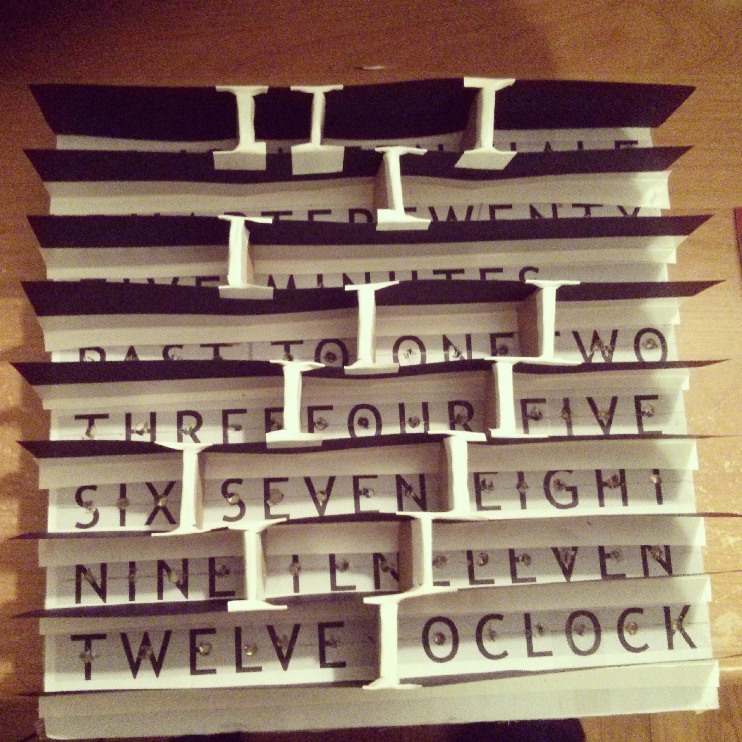
On the front of the LED board, I blocked off each section by first cutting strips of oaktag paper to block off each row, and next block off each word with a small piece of cardboard. Â Each word is blocked out so words not lit appear dark. Â It will take some adjusting to get things looking proper during the final assembly. Â Behind the front face stencil, I included a piece of dark tissue paper to filter the light though and create a nice effect.
Mount everything else inside your display case (I used a shadowbox purchased at a local craft store), and you are done!
Here is a schematic of the clock:
Posted: Dec 24, 2013
Keyword tags: arduinoelectronicsclockRTCshift registers
Recent Posts:
Popular Posts:
Recent Security Posts:
S3 Buckets: Now With Both Leak & Fill Vulnerability
Stealing Data With CSS: Attack and Defense
Move Over S3: Open Directory Indexes Continue to be a Problem
Security Researchers Lose a Favorite DNS Recon Tool Jan 2018
KRACK: How To Protect Yourself on a Flawed Network
Equifax, SEC, & Now Deloitte: Organizations Must Employ Offensive Security
securityconference talkinfoseccybersecuritypurple teamoffensivesecurityhackingred teamlinuxvulnerability disclosureweb securitys3electronicsmakeremote vulnerabilitylets encryptphishingarduinoamateur radiocircuitsdoorbellschematicandroidOS warsmartphonetabletsfutureiPhoneUXopen source software

Visit makeRF, my website devoted to amateur radio experments and electronics.